FEA Finite Element Analysis
The key to a good analysis is a knowledge of the limitations of the method, and an
understanding of the physical phenomena under investigation
F. E .A. Finite Element Analysis. We will be a member of your team as expert consultants. Our goal is to offer our clients the most cost effective, best practice solutions, and deliver them on schedule.
Detroit Design Engineering can offer expert recommendations, council concerning material savings, value analysis, component analysis, and redesign for all parts.
FEA Finite Element Analysis Tools:
- NE Nastran
- FEMAP
- Structural
- Stress
- Force Deflection
- Static and Non Linear Analysis
- Modal Analysis (Natural Frequencies)
Structural analysis provided through a Finite Element Analysis (FEA) helps the customer to design a part that meets the demanding strength and stress requirements in today’s market place. Finite element analysis (FEA) can prevent the product from being over or under engineered, an over engineered product wastes material, while an under engineered product can lead to failures which will waste time, and money through expensive tooling changes. Detroit Design Engineers will conduct a finite element analysis (FEA) on your component, and make recommendations to improve the parts being tested. Even if you are confident in your design, the finite element analysis (FEA) can help prove the functionality of your component to your customer.
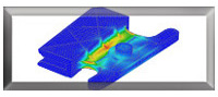
FEA example #1
In the Finite Element Analysis (FEA) shown in example one, there was a structural stress analysis preformed on a window glass mount. In this example there are three different animations showing the progression of the part through added structure and design changes. In the Initial Finite element analysis (FEA) the product was analyzed as initially modeled. The results for the first iteration on this mount gave us a stress over 13,000 PSI, which was well above the passing level for this component. After Detroit Design engineers made changes to the math data an additional iteration was ran as seen in the second animation. This second analysis shows us a stress level of 3948 PSI. In order to provide a increased factor of safety for this window mount, a few more changes where made to the cad model and the analysis was ran again giving us this third iteration. The stress in this final analysis was 2,959 PSI, a total reduction from case #1 to case #3 of over 10,000 PSI.
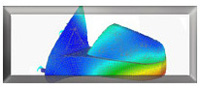
FEA example #2
In the Finite Element Analysis (FEA) shown in example #2 there is Modal analysis being ran on a mirror assembly. The Modal analysis ran in this case gave Detroit Design Engineers and our customer the information necessary to raise natural frequency to a higher level.
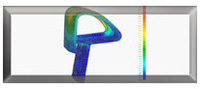
FEA example #3
In the Finite Element Analysis (FEA) shown in example #3 Detroit Design Engineering ran an analysis on a bumper. The bumper Finite Element Analysis (FEA) shown in the first animation was conducted on the original design. After applying the appropriate load to the bumper and running the analysis, the Finite Element Analysis (FEA) results indicated that the bumper was expected to fail. After discussions with our customer and a couple of meetings, Detroit Design Engineers redesigned the bumper. The second animation shown is an analysis of this modified design. An additional redesign was conducted as shown in the third and final iteration. This iteration created a successful bumper that had an acceptable stress level and at the same time gave the flexibility desired for this component.
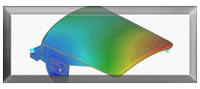
FEA example #4
This Finite Element Analysis (FEA) example shows a typical force deflection study. The desired resistance to deflection under load is calculated to show the components rigidity, as well as the anticipated stress levels.